TD5 - Engine Oil Pump Bolt
"TD5 Engine Oil Pump Bolt" (Including Power Steering pipe Issue)
Just like every make and model, the Discovery 2 has its share of “known issues”—ones that are well-circulated among owners and, hopefully, recognized by the manufacturers too. One of the most notorious problems? The infamous oil pump bolt.
It’s a seemingly simple 10mm-headed bolt that secures the oil pump sprocket down in the sump. However, it’s a well-documented fact that these bolts can (and do) work loose over time. If the bolt falls out, the sprocket detaches—cutting off oil circulation and ultimately leading to catastrophic engine failure.

Land Rover were reportedly aware of this issue, and it’s believed that they replaced a number of affected engines under warranty. The root of the problem lies in the factory installation of the bolt—with no thread lock applied. Without it, the bolt can work loose over time, potentially leading to catastrophic engine failure.
From what I understand, the issue came to light during the early production of the TD5 engine in the Discovery 2, and was eventually addressed at the manufacturing stage. That said, earlier models are still considered the most vulnerable. However, I’ve read accounts of 2003 and 2004 vehicles where inspections revealed the bolt was still loose, suggesting the risk may extend beyond just the initial production run.
Given this potential problem—plus the fact that 1) my car was due for an oil change and 2) the sump gasket had started to weep...

I figured it wouldn’t hurt to inspect or replace the oil pump bolt while tackling the other two jobs—it just made sense to combine them.
To start, the car needs to be jacked up and supported as high as possible from the chassis to allow the front axle to drop, giving you clearance to remove the sump. Initially, I supported mine on the front cross member, but quickly realised that had to come off to access the sump. The workshop manual does mention this, though as we all know, it tends to sugarcoat the job. In this case, though, there’s no workaround—removing the cross member is essential.
You can take it off by undoing the eight bolts—four on each side. If they’re a bit corroded, a good soaking with WD40 beforehand makes the task much easier.

Once the vehicle is raised and secured, drain the engine oil as usual. When the flow slows to a stop, refit the sump plug temporarily to avoid any lingering drips while you're working underneath.
Next, remove the plastic under shields—assuming they're still fitted. With those out of the way, locate and remove the “P” clip securing the left-hand gearbox oil cooler pipe to the front of the sump.
Next, undo the clamp that also holds this pipe on the drivers side of the car, this will allow you to flex the pipe out the way when removing the sump.

Now at the back of the sump, there is 4 bolts running forwards that go through the bell housing and into the sump. Remove all 4 of these.
3 can be seen in this picture, the one you cannot see is directly on the opposite side. All 4 of these bolts are the same length / type, but it is good practice to note which one went where for re-assembly later on.
Now undo and remove either the 2 bolts, or nuts on the drain tube from the centrifugal oil filter.

Remove them completely and the pipe will stay sat on the studs and help support the sump when you remove it. If you have bolts, then it may be a good idea to leave them in just 2 or 3 threads so you can easily remove them by hand when the sump is ready to come off, but they will help support it whilst temporarily left in.
Now its a case of undoing the remaining sump bolts. The is a required sequence to do this, so I have copied it here below directly from the workshop manual.

Now, most of the bolts are the same length, except the ones nearest the bell housing. There is 3 different lengths here, so you MUST note their original fitted positions. To save any possible error or confusion when it comes to the refit, you could do what I did and simply get a piece of cardboard and draw the shape of the sump on it, and each time you remove a bolt, poke it through the cardboard in the relative position it came from and number either a few for reference or all of them.
When it comes to the last bolt, remember the sump is cast aluminum so avoid dropping it at all costs, also remember either the 2 bolts or nuts holding the rotor filter drain tube, remove them and manouver the sump down and out to the rear of the car.
The workshop manual states to also remove the exhaust front pipe, I chose to try it without disturbing that and it does actually come out easily with the front pipe still installed.
Here's the sump below, as you can see there's ALWAYS some old oil you just cannot get out with a normal drain and refill !!

My Sump gasket was actually weeping from the top left corner (looking at picture above), later you will see why...
Right, now the sump is off, you will be able to see the famous bolt!!!. I'm not to sure what I wanted to find really, if it had been half out ( as has happened) then it would have been a great sigh of relief, how ever, mine was definitely still in there, although it was a "little" loose for my liking, so I'm glad I checked it anyway.

The Pump bolt was superseded by a new part that has thread lock already on it, so its just a case of carefully removing the bolt and installing the new one. Keep hold of the sprocket to make sure it stays in position when you take the bolt out.
Here's the new bolt below, you can clearly see the thread lock all ready on it. The old bolt did not really show any signs of thread lock at all.

Simply fit the new bolt into the pump sprocket and tighten / torque it up to 25NM, 18Lbs FT or 216 Lbs IN depending on your torque wrench. A 3/8 drive torque wrench is about the right size and probably the biggest you can fit into the space to torque it up with.

Whilst the sump was off, I took the opportunity to give it a full clean / degrease both inside and out. Below is the clean sump with a new gasket installed.

The gasket has molded dowels on it to make sure it locates correctly both on the sump and on the bottom of the cylinder block. The gasket is installed DRY.
Now before the refit, You need to carefully clean the mating face of the cylinder block with some clean rag or tissue. While I was doing this I noticed what the next job would be :o(
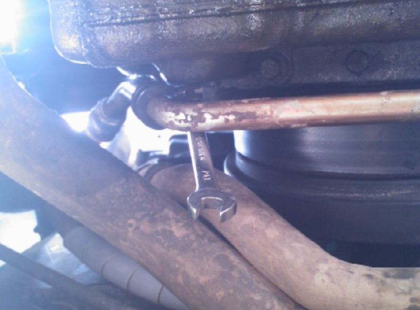
At the front left corner of the sump, the power steering pipe coming down from the reservoir passes the sump VERY closely on its way up to the pump, in fact its too bloody close as it has been chaffing away and was only a matter of time before it made a hole in the pipe.
If you look at the picture below you will see the damage that has been done to the pipe.

This pipe is a solid metal and rubber pipe. The damage here is at least 50% through the thickness of the metal part of the pipe. Now that have found it and moved it away it would most likely be ok, but I will replace this at the earliest opportunity. Land Rover in their wisdom fitted a pathetic piece of foam to stop this pipe chaffing, but as you can see it didn't really work. A simple bracket and "P" clip would have been the correct way to do it.
Below you can also see how much of the edge of the sump the pipe has worn away.

The Pipe is now currently tie-wrapped securely out the way of the sump, once I get a replacement pipe, I will make a bracket and fit a "p" clip to hold it and stop it ever happening again. After writing this article, I did a little research and this is a VERY common issue, although its generally found once it has actually holed the pipe.
The new pipe is Part No ANR6974 and is around £20 inc VAT.
The rotor filter drain tube has a metal crushable type gasket on it, I never got a replacement in time to do this job, so I was careful when cleaning the sump and re-used the original gasket. If it leaks then I will have to replace it at a later date, but this could be done with everything installed on the car as normal. The gasket is supposed to be installed dry, but I applied a small smear of Hylomar when I refitted it to help hold it in place.
Before the final refit, you must put a small bead of sealant in the places marked below on the diagram. Once the sealant is applied you should aim to get the sump re-fitted and torqued up within 20 mins. The workshop manual calls for a sealant of PN RTC3254 if you wish to use the genuine product, but any good quality oil resistant silicone RTV sealant will suffice, Halfords do stock a suitable product.

Now its a case of re-fitting the sump back to the engine. Carefully move it into position trying not to disturb the new gasket and not hitting the bottom of the car so dirt / dust etc falls into the sump. Its a little bit fiddly to do on your own, but take your time when doing it. Fit ALL the bolts in by hand first including the 4 bolts that go through the bell housing. This is where you MUST make sure you fit the correct length bolt in the correct position.
As with the loosening sequence, there is also a correct tightening / torque sequence of the sump bolts. (below)

Tighten / Torque all the sump bolts to 25NM , 18LbS ft or 216 Lbs IN
Tighten the 4 bolts that go through the bell housing to 13NM or 10LBS ft. Then refit the gasket and either the bolts or nuts on the rotor filter drain tube and torque to 10NM or 7LBS ft
Refit the "P" clip securing the Oil cooler pipe to the front of the sump, and refit (if removed) the bracket holding the oil cooler pipes on the right hand side of the engine (looking forward).
The rest of the refit is a reverse of the removal. Once everything is refitted, change the 2 oil filters as per the standard oil change page and then refill the oil to the correct level and run the engine up to operating temperature to check for leaks.